DIY Motion Simulator
- Part 1 – Project overview – What is it and what is it so much fun? 😉
- Introduction, what is this about?
- Showcase of the completed project (with video!)
- The “SFX-100” project
- Bill of materials and cost breakdown
- 3D printed parts
- Competitive landscape and price comparison
- Manuals for motors and controllers (download links)
- Part 2 – Electronics
- Part 3 – Linear actuators
- Part 4 – The rig
This is a part 4 of 4 – access all the sections of this series by using the index above.
Part 4 – Rig, monitor stand, accessories
Now that we have the actuators, we need to mount it to something… 😉
There are many ways to build your racing cockpit. You can use wood, PVC pipes, custom shaped steel pipes, and more. Many different companies offer custom solutions, or you can stick to one of the popular offerings. I chose to take the path of building out of aluminum extrusions.
Rigs built out of aluminum extrusions are very popular, for good reasons:
- sturdiness – they can handle Direct Drive wheels, monitors installed directly to the rig, and of course: motion,
- customization – aluminum extrusions are almost like LEGO, you can design your own thing, add various attachments, and the variety of brackets and mounting options guarantees that your project can be done. If one day you want to turn it into a flight sim – you can do that. And if, for some reason, you decide that this hobby is no longer for you, those materials are strong enough to make for some heavy-duty shelving or something 😉
Sim-Lab P1-X
Sim-Lab is very well known in the circle of sim racers. They offer high-quality products at an affordable prices. They’re in Europe (Netherlands), so shipping to US costs a bit more and takes few days. Additionally, their products are often out of stock, so plan accordingly. They’re growing, and sometimes the popularity can exceed their capacity, but it’s worth waiting and getting the right equipment the first time, instead of going with something less proven.
I’ve ordered my parts at the peak of Black Friday shopping of 2019, and because of the volume of orders they had to deal with, I received my packages mid-January 2020. Again – worth the wait.
Here’s a timelapse I made showing the assembly of P1-X:
You can see that the progress slowed down around the part where I had to install the seat – that was one step that tuerned out to be a bit tricky, but we’ll get to that.
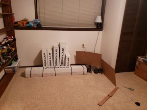
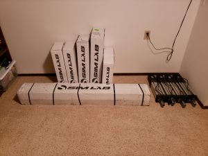
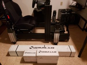
As many good builds do, this one began with a lot of boxes full of parts:
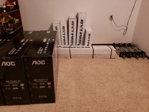
You can see cardboard cutouts I used to visualize the 3x 32″ monitors, to see where I’d like to position the rig. And the actuators are visible on the side, ready to be attached once we build the rig.
Please refer to bill of materials to see what all came in the boxes. I accessorized the rig following the principle of “buy once, cry one” 😉
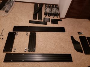
There are many pieces required to put it together – organizing them can help with the process, especially when decided which parts to use (e.g. there are different sizes of t-nuts, for M6 and M8):
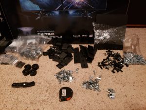
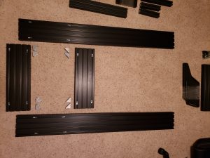
I began by laying out the pieces, and placing brackets, bolts and t-nuts where they will be needed:
It helps to plan ahead, especially if there’s any uncertainty as to what piece is for what. Seeing where they fit best from the beginning is a great confirmation that we’re not building something unexpected, which we will have to then rebuild, upon realizing some mistakes.
One important thing when assembling the base – the spacing for the 2 pieces sandwiched in between the long side profiles can be determined by placing the seat rails on top of them:
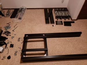
Check that the distances are same on both sides and that the base is square.
Having the base put together, make sure to tighten all the bolts, then put the plastic caps onto the brackets to finish the look:
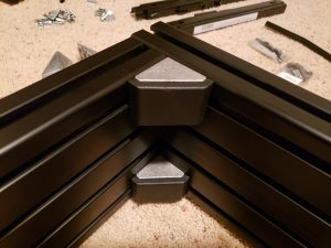
Next, I measured equal distance from each end, and put the feet into the side profiles:
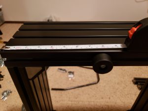
This isn’t an absolute necessity, especially considering that we’ll be adding motion and the whole rig will be supported by actuators, but if I ever have to remove actuators, those feet will protect the profiles from getting scratched on the floor (or damaging the floor).
Time to assemble the pedal tray. It’s been redesigned for P1-X (compared to previous model, the P1), and is really strong. There’s no way it will flex, even if you use some ridiculously hard (100kg+) brake pedals. Just look at those profiles:
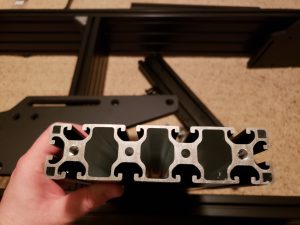
Thing to note: the pedal tray can be installed in 4 different orientations, depending on your preferences. It can be pointing forwards or backwards, and with the side supports being underneath or above the pedal tray. This way you can configure it for anything from road cars, through GT, to Formula style seating.
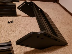
At first I decided on this configuration, with the “nose” pointing forward, and supports being underneath:
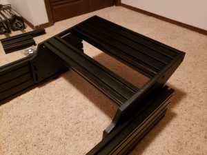
However after some tests I flipped it so that the “nose” points towards the seat – this allowed me for more comfortable range of adjustments.
One thing that surprised me with the pedal tray was the fact that there were screws of different lengths in the packaging. I recommend comparing them and using all of the same length:
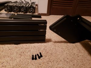
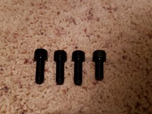
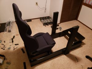
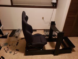
At this point the rig is starting to resemble something 🙂
Next step – installing the seat. I decided to purchase seat slider – they’re built strong (it’s not a sim racing specific hardware – the same piece is installed in cars), thus doesn’t carry risk of being unstable when used with motion. It does however provide the benefit of quick and convenient adjustment when someone else is using the rig, of if you want to quickly demo it to someone.
My slider is made by Sparco, and comes with a bag of hardware to install a variety of seats:
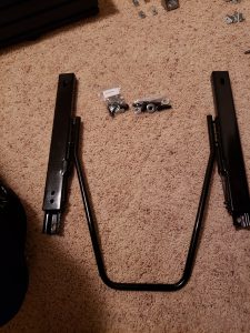
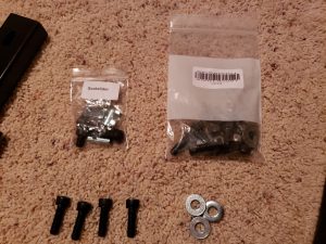
It took me a while to figure out in what orientation should be installed – which side is to be bolted to the seat, and which one to the aluminum extrusions. This is how it’s intended to be set up:
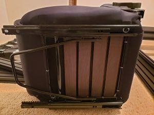
Before dropping the seat onto extrusions, I quickly measured the needed distance between profiles to accommodate slider and make the installation easier:
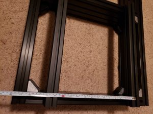
We still need to attach the 2 profiles to which slider will be bolted, so it’s time to grab few bolts, t-nuts and brackets. This is a first configuration in which we actually need to modify the brackets.
The brackets come with alignment tabs on each side. Those small bits fit into the gap in the extrusion, and make it easier to position things and make sure everything is square. However, if they’re being installed at a 90 degree angle to the direction of the extrussion, we need to snap them off to allow for flush fit of the bracket and aluminum profile. Not every bracket is same, and depending on where you sourced your parts it may either take a second, or require you to use some power tools. Luckily, Sim-Lab chose a high quality components.
To snap off the tabs (remember, we want to do it only on 1 side of each of the brackets used to install seat supports), use a flat screw driver, insert it into the hole next to the tab and simply twist:
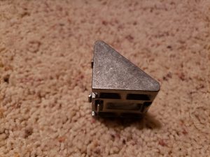
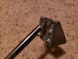
Tabs should cleanly snap right off:
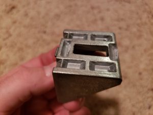
Use the modified brackets to attach the seat supports, but don’t fully tighten them just yet, as we’ll adjust them as needed upon adding the seat:
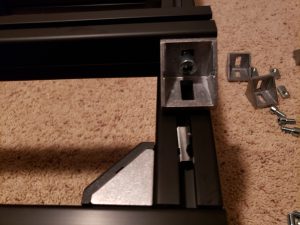
Now, place the seat on supports:
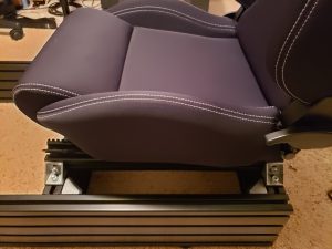
Push in t-nuts into the profiles and both the bottom side of the sliders to supports:
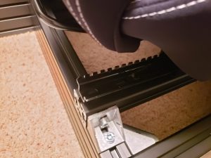
Move the seat forwards and backwards in the sliders, as needed, to expose the holes for bolts:
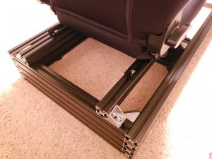
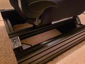
To confirm that the seat is installed properly, do a quick test: move the seat as far front as possible, and then as far back as it will go. Does it move freely, or does it get stuck unexpectedly? If it’s installed right and square on the profiles, it will move easily. Adjust as needed until the results are to your expectations, it’s not a long process.
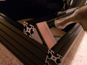
Once everything is bolted on, add black caps on the brackets. Here’s a tip: I used a piece of the thick cardboard material that the profiles were secured with during the transport, and then hit it with hammer couple of times. This is an easy way to prevent damaging the caps:
And the seat is installed! Be sure to try it out and see if it’s comfortable 😉
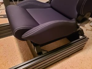
If you just sat in the newly installed seat, you probably wondered – but where’s the steering wheel? Well, this is what we’ll take care of next. If you look at the remaining parts, we have 2 profiles (120x40mm), and 2 plates:
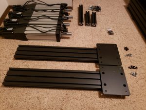
Let’s attach the plates flush with one end of the profiles, using bolts and t-nuts:
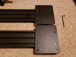
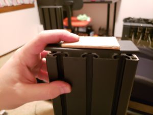
Next, grab the end caps and a hammer (I also recommend using some protective piece in between to avoid scratching the plastic, same one I used before for bracket caps), and install the end caps on the wheel deck uprights:
Next, align the uprights with the base, make sure they’re in the same distance from the ends on each side, and bolt them on, using yet another set of bolts and t-nuts:
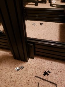
Don’t fully tighten them just yet – have a seat and find the best location, or better yet – wait for few more minutes, and try it out with the wheel deck installed, before tightening all the screws.
This step may be different, depending on which variant you ordered. I went with wheel deck, as it seems robust enough to accommodate the wheel I’m currently using, as well as the one I’m thinking of upgrading to (the never-ending sim racing journey… 🙂 ).
Look-up the bag with relevant hardware:
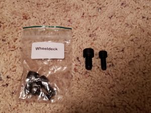
Insert 2 t-nuts for each of the 2 wheel supports:
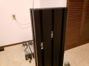
And attach the wheel deck, trying to keep it at the same height on each side:
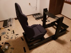
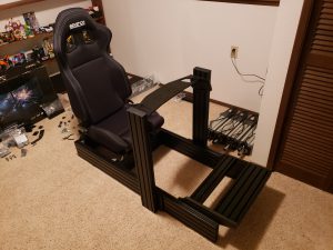
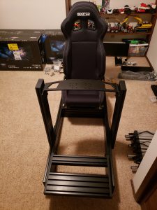
With the deck in place, it should be easier to estimate how far forward should the wheel supports be positioned. Once you find the optimal configuration, tighten all the screws (the ones on the plates attached to wheel uprights, as well as the ones holding the wheel deck).
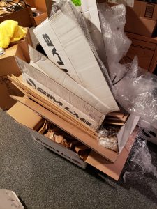
Phew, that was quite some work, and just take a look at the pile of now empty boxes!
Improved lever-screws for easy adjustment of the wheel position
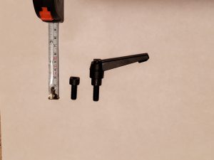
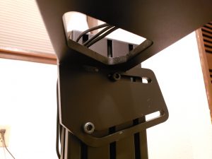
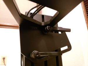
I purchased some lever-type screws, which allow you to pull on the lever in order to move it without affecting the screw, so that you can operate the screw with hand, even in somewhat limited spaces. This way we can quickly loosen/tighten the steering wheel mount to make quick adjustments.
See bill of materials for product links.
It’s so much easier to adjust the wheel height and angle, to make it comfortable for everyone using the rig, when proudly showing your build to others 🙂
[back to index]
Attaching the actuators to the rig
Preparing the brackets
I purchased black brackets to match the anodized aluminum used for the rig. However, they didn’t come with easy to snap alignment tabs. Goes to show the quality of Sim-Lab components… I tried few things: breaking the tabs with pliers (difficult, doesn’t break cleanly), trying to snap them with a screw driver and a hammer (weird combination, didn’t work very well), sanding them off (dusty, takes forever)… What worked was clamping them in a vise, and cutting the tabs with an electric jigsaw.
Warning: be sure to wear eye protection. You don’t want aluminum shavings in your eyes!
With the jigsaw, it took around 10 minutes to prepare a full set of brackets (4 for each actuator, 16 total – but while at it I also made few extra to have for later modifications):
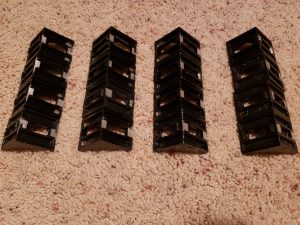
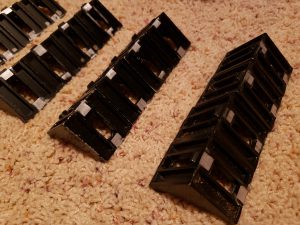
Notice that we need to remove the alignment tabs only for one side of each bracket.
Note: before proceeding further, make sure that in addition to the t-nuts provided by Sim-Lab, you also have additional t-nuts for the K45/K50 profiles. Those can be ordered along with the actuator profiles from Kinetik. Those profile are larger than Sim-Labs, thus need wider t-nuts. Refer to bill of materials for more information.
Attaching actuators
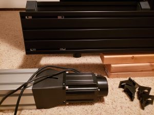
As I mentioned, I’m using 4 brackets per actuator. At first I was considering adding 1 or 2 brackets also at the top of actuators, but I quickly realized there’s really no need for that. Thus you may see some unnecessary brackets at the image below, taken as I was getting ready for the installation:
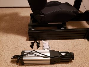
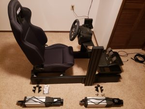
We need to lift the rig to a sufficient height in order to be able to attach actuators. Depending on your rig, it can be quite heavy. Especially if it’s already fully assembled, with the seat, steering wheel, pedals and other accessories.
I found that having 3 pieces of 2″ x 4″ scrap wood gave the perfect height. I lifted one side at a time and propped it. The bottom of the rig is unlikely to get scratched that way.
Then it’s all a matter of attaching the brackets to the actuator side first, using the 45/50 profile T-Nuts ordered from Kinetik (note that those are different size than T-nuts provided by Sim-Lab!). Don’t tighten the brackets on the actuator just yet, to allow for adjustment when putting the screws from the rig side:
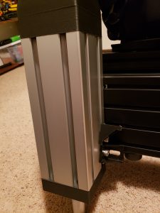
And then put in t-nuts into the rig profile (now you can use the ones from Sim-Lab), position them in the right place, and put in screws through the brackets attached to actuators:
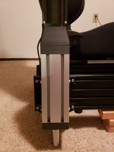
Before tightening all the screws, make sure that:
- the brackets are close to the bottom edge of the actuators (we want the rig to sit as low as possible),
- actuators are straight, and their side adjacent to the rig is parallel to the rig (they may be trying to lean to the side before you tighten all the bolts),
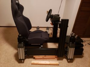
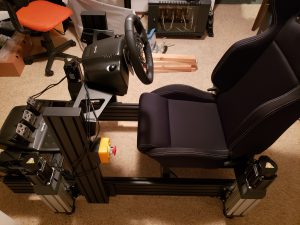
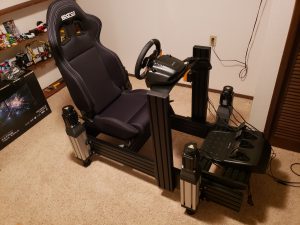
Repeat the process on all four corners, installing rear actuators as far rear as possible on your rig (with the goal of having the seat as close to the center point between all actuators as practically possible), and front actuators just in front of the steering wheel column:
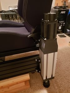
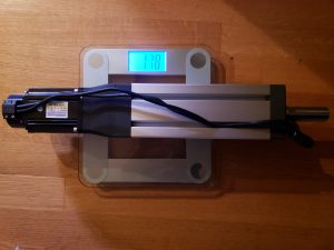
Actuator weight: have you wondered how heavy are the actuators? Looks like they clock in at just under 18 pounds a piece:
Attaching emergency stop button
It’s an important element – I’ve never had to use mine, but it’s one of those things that it’s better to have and not use, than not have and need to use… Especially if you have pets or small kids, having a thing that can prevent an accident can’t be overestimated. So just do it – see instructions above for wiring such switch.
And when it comes to installing it onto the rig: use 2 t-nuts and bolts, screw the base to the rig, screw the top part of the button, route the cable so it doesn’t get in the way and done:
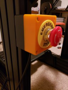
There are many good places to install it, but make sure it’s easily accessible (e.g. always within a reach, even if you’re strapped in the harness).
Cable management
Tangled cables everywhere are not very practical, make any changes unnecessary annoying, and a rat nest next to your rig is just an eye-sore 😉 Cleaning the wiring is a one-time job that is a nice finishing-touch and increases the appeal of final project.
And there are definitely a lot of cables to take care of, the cables for motion are just a part of it:
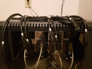
There are 2 cables going from controllers to each of the actuators – power and data (encoder). They’re quick thick, but not very long – effective routing will give you more flexibility when it comes to the placement of the cabinet with controllers.
This is where on trick yields great benefits – the motor cable connectors fit inside the aluminum extrusions. That means we can route, depending on where we want for all the cables to leave the rig, route the cables from either the front or the rear pair of actuators through the channels inside the side extrusions:
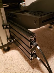
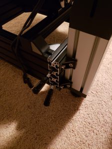
I router cables from rear actuators to the front of the rig, where all the cables come together.
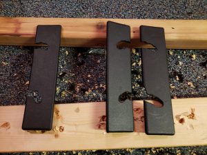
Now to finish it up, let’s take the plastic caps and cut holes for cables:
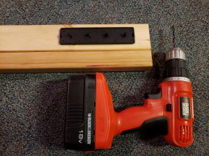
Using a drill we can quickly get the desired results. Note that I cut the openings at an angle, so that the cables naturally stay in the middle of the hole (this is why the direction of those openings is different between caps for left and right side of the rig):
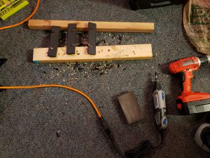
I used few different products to organize all the cables: zip ties, velcro cable ties (if you have to choose one of those 2, skip zip ties – velcro ones are re-usable and easier to work with when making changes), cable spiral and a cable sleeve. See bill of materials for all product listings.
The cable spiral is great to wrap the motor cables:
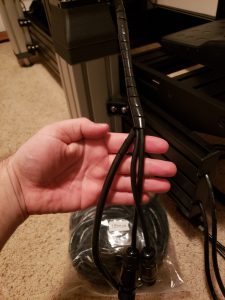
As well as bundle all the cables for accessories (steering wheel power cable, connection to pedals and connection to PC):
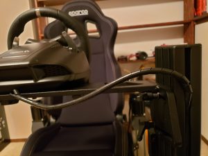
Now with a bundle of cables meeting at the front of the rig, we can sort them out. This is where I used some cable sleeves (I like the ones with velcro, since then can be cut to size and easily opened to make modifications). Using them in combination with the cable spiral, zip ties and 80/20 cable clips leads to decent results:
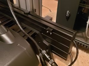
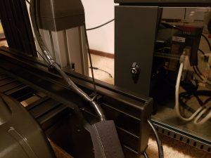
And we end up with a single bundle going to the cabinet with electronics:
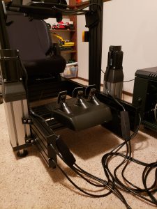
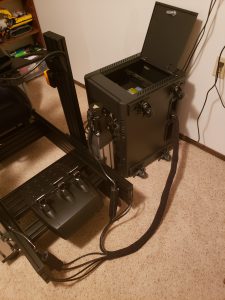
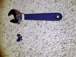
Here’s the 80/20 cable clip. Those are really handy – fit into the extrusion channels, stay in place and provide anchoring points for zip ties. It takes quite a bit of force to insert them into the profile, use an adjustable wrench to help with that (just be sure not to scratch the profiles in the process, be careful):
Now, doesn’t that look much cleaner without cables getting in the way?
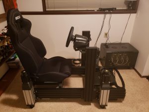
(ignore the cables on window sill for now 😉 )
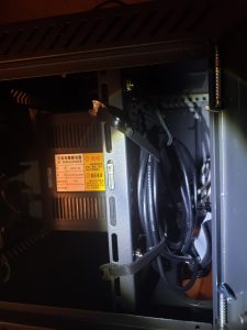
One thing, that isn’t really easy to notice, is stashing the extra lengths of the cables. I wrapped them and put inside the cabinet, mounting it to the back of the plate with controllers:
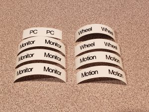
And if you read that far, you know by now that I like to use label maker, so I whipped it out to also get labels for all the power cables 😉
What if I want to design my own rig?
There are few ways to approach that – you can build something out of wood, PVC pipes (although I wouldn’t recommend if the rig is to be used with motion), or still using aluminum profiles, but just your custom design.
If you want to stick to aluminum extrusions, this is a handy piece of software that allows for designing out of that material:
MAY-CAD
http://www.may-cad.org/en/p1.htm
It’s available for free and offers an extensive library of various parts.
And if you start feeling limited by its capabilities, there’s always Fusion 360 😉
Building the monitor stand
I was so happy when I saw another set of white boxes appear at my doorstep – that much closer to finishing the build! 🙂
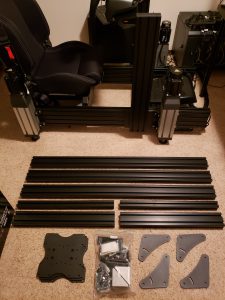
I laid down all the pieces to get a good look, make sure everything that we need is here, there’s no damage, and plan for the assembly:
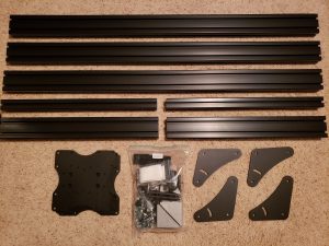
Looking at the VESA plates and the thickness of the profiles you may quickly recognize that this is the “heavy” variant of the monitor stand offered by Sim-Lab.
And as always, check out the bill of materials for product links.
I’ve you’ve been following products from Sim-Lab carefully, you may notice that some of the elements in this stand have been modified. E.g. we’re now using regular brackets to attach the horizontal “feet” extrusions to the legs instead of previously used plates. Compare the above pieces with what you see in the review from Sim Racing Garage (Barry makes awesome, detailed review) if you’re curious about the details.
Make sure you have enough room around the rig for assembly. Assembling it on the spot has the benefit of not needing to re-position it once it’s already put together, as with the monitors attached things get quite heavy.
All those pieces don’t really come with a manual, but this is a gap I’m hoping to fill with my series of articles on this subject after all 🙂
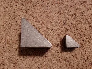
One thing that caught my attention upon closer examination is the difference in size between the large brackets, which are used to attach the horizontal beams with monitors to the vertical legs of the stand. The large brackets accommodate 2 rows of 2 t-nuts on each side, as opposite to 1 t-nut per side for small brackets:
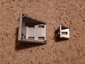
Alright, time to rip the bags with small parts open and get to the assembly:
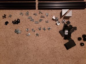
It’s really simple – we need to have 2 legs, and then 3 horizontal beams: one in the center, connecting the 2 legs, and then 2 on the sides for left and right monitor. The center beam is the same size as the horizontal beams used for legs – this is an easy way to identify the purpose of each piece of aluminum profile.
I began by breaking off the alignment tabs from one side of the 2 large brackets, and then attaching the brackets to the center beam (leaving the side with tabs removed exposed):
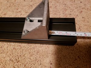
I later aligned the spacing between legs to ensure sufficient room for the rig underneath, considering the motion… As such, the above measurements are the minimum I’d recommend.
Then I attached the legs to the center beam – ask for help if you can, as having someone hold the pieces while you’re putting in the bolts makes it way easier. Also be sure to insert the t-nuts first, before lifting the pieces and aligning them in place, but this should come naturally at this point, after assembling the rig.
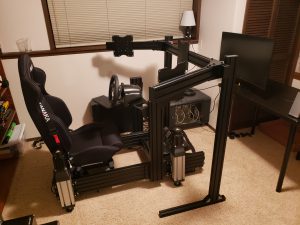
And here we are with the center piece standing, and sides being ready for assembly. Adding the L-shaped plates onto the side profiles allows for easy installation even without help from someone else to hold them in place:
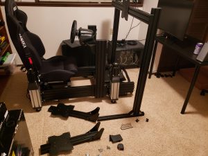
Note: do not fully tighten the bolts holding the side arms yet. We will need the ability to fine tune their position to align all 3 monitors.
If you’re using 32″ or larger monitors, I recommend bringing the horizontal extrusions as far up as possible, flush with the end of horizontal uprights. This will depend on the wheel base you’re using, but with actuators fully extended, I was getting uncomfortably close with the rig to monitors, thus I later decided to lift them higher. It’s way easier to do at this stage, without the added weight of the monitors.
Speaking of which, this is the time to unpack monitors, keep all the cables and stands they came with on the side, and prepare the spacers:
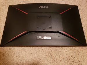
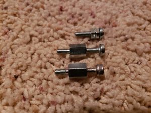
Depending on your monitors, you may or may not need the spacer, but you probably will 🙂 I actually ordered an extra set, as I wasn’t sure if they will come with the parts for stand, but I was positively surprised to see Sim-Lab already included them.
I checked bolts that came in the set from Sim-Lab, but they were either too short or too long for the thickness of VESA plate… So instead, I grabbed M4 x 12mm from a set I have (check out bill of materials, it’s often useful to have an assortment of those at hand):
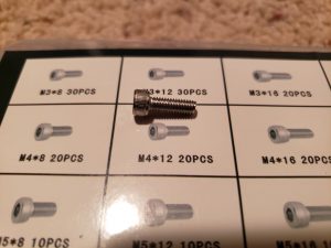
Now, having monitors bolted onto the VESA plates, and the plates attached to the stand arms, we realize the biggest design flaw of this stand – in order to re-position the plates on arms, we need to remove monitors first. This is something I believe Sim-Lab is addressing by changing the installation method to use brackets to attach the VESA plates, so that brackets are accessible and can be loosened/tightened, without having to remove monitors.
Don’t get me wrong, this stand is still awesome despite the above limitation.
But in all honesty, it took me nearly 2 hours to fine-tune the position of the side monitors (center one was easy, just install it in the middle of the center beam). Changing the angles often required further tweaks to make sure the bezels meet exactly where I need them to meet.
Luckily this is a one-time setup, and it pays to get it done right, so be patient and at some point you’ll arrive at great results 🙂
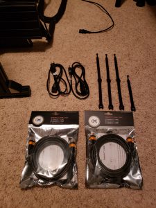
Now all that is left is to connect all the monitors. I skipped the cables provided in the boxes, as they were fairly short, and instead opted for 2x 13ft (for left and right monitors) and 1x 10ft (for center) Display Port cables. Those worked great:
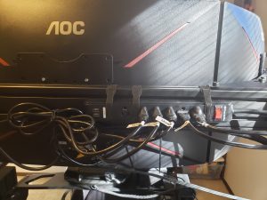
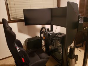
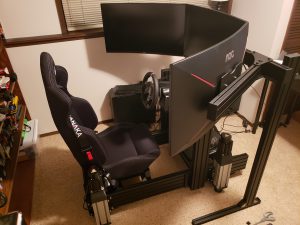
After some cable management (I installed a power strip in the back of the center monitor, so that I only need 1 power plug for the complete triple monitor setup), and organizing the 3 Display Ports cables with a cable spiral, the results look very clean:
Couple final things to check, considering that we’ll be using the triple monitor stand in combination with motion rig:
-
clearance to the sides – the rig will tilt significantly, make sure nothing will hit the legs of the monitor stand,
-
clearance under the monitors – as the rig moves up and down, it’s critical to verify that rig at the max height doesn’t come in contact with the monitors,
And here’s a quick before and after:
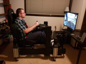
Before – one monitor, and don’t even mention the FOV…
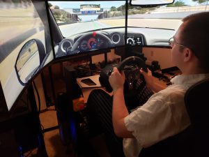
After – the way sim racing is intended!
Configuring the FOV
This is usually quite controversial subject… 🙂 It’s important to have the field of view set correctly, if possible, as it makes it feel much more natural. And after all, it’s simulation of the reality we’re after, isn’t it?
I’ll just leave you with few handy links that should help you understand this subject better than I can explain, and arrive at the right values for your configuration:
https://dinex86.github.io/FOV-Calculator/
http://www.edracing.com/edr/FOV.php
Extra: Accessories and customization
You may know that already – and if not, you’ll learn soon enough 😉 – but the build never really ends. The temptation of upgrading your hardware is strong – Direct drive? New wheels? Upgraded pedals? Shifter? Handbrake? VR?
Below I’m listing some of less-common improvements and modification I’ve made.
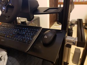
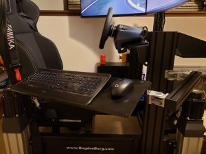
Keyboard tray
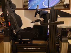
That’s a must have – we need keyboard to use a PC. Having keyboard on the side on a single joint is the most common approach. However, if we’re investing in the gaming PC, it’s nice to be able to use it comfortably for long period of times also when not racing. This is why it was important for me to have the keyboard in the normal place – right in front of me, above my lap.
I used one of the extra profiles provided with P1-X and ordered additional 40mm joint. This allows me to adjust the keyboard’s position, as well as move it out of the way when getting in/out of the seat.
The tray itself is wide enough to accommodate keyboard (well, most of it) and mouse on the side:
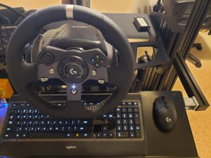
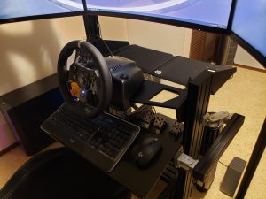
That’s how it looks in relation to the monitors:
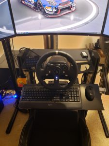
Note that the rig is at a resting position, with motion disabled – this is why such a large gap under the monitors.
The arm allows for convenient adjustment – 2 hinges enable me to pull the keyboard a bit closer, or push it away.
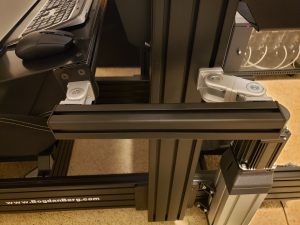
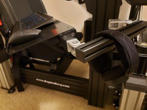
It’s also a great place to hang the headphones 🙂
Shelf behind the wheel
The space behind the wheel, right above the pedals, is often left unused. But it doesn’t have to be like that. This is a convenient location to keep your phone while you’re racing, or put down the gloves once you’re done. Or maybe you’d like to keep a small notepad to take notes from your practice sessions?
Adding this shelf is a cheap and easy way to provide more utility for your rig:
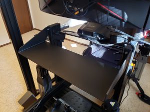
That shelf was also purchased from Sim-Lab, see bill of materials.
Mouse pads
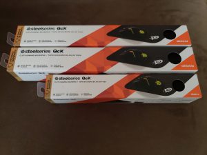
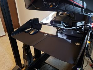
I used mouse pads to line both the shelf behind the wheel, for more luxurious feel 😉 as well as the mouse pad installed onto the rig. The classic Steelseries design is fair priced and available in few different sized. I ended up using 2 Medium and 1 Small:
And this is how the shelf looks with mousepads – makes it feel a bit more upscale 😉
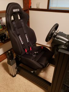
Harness
We always use seat belts when driving a real car, it’s the smart thing to do. And there’s something about that being an integral part of the experience.
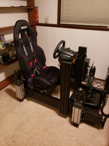
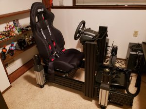
At first I was skeptical whether using 4-point harness won’t be a hassle when sim racing, since it’s not like it’s needed on the simulator. But after I tried it for the first time – it feels great!
Link to the harness I’m using is available in the bill of materials, but here it is directly on Amazon.
Photos taken right after installing the harness. I didn’t have the monitor stand yet:
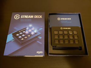
Stream Deck
This is a fairly common addition to rigs, used by many sim racers. In addition to, or even instead of using regular button boxes, having one of those provides us with an easy way to quickly perform specific actions. Thanks to ability to configure Stream Deck for each game, // TODO: finish, re-write
I like how configurable StreamDeck is – in a matter of minutes you can set the views with exactly the functions you need.
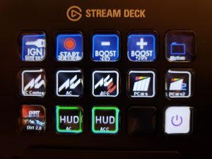
Here are my 2 screens: main menu, including options for the motion (‘Ignition’ starts SimFeedback, ‘Start’ activated motion profile, and ‘Boost +/-‘ change the intensity):
and a screen dedicated to Assetto Corsa Competizione:
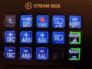
With a button box like that, you can get by even without button box on the steering wheel. Although it’s most convenient to have both…
There’s a number of icons dedicated to sim racing, available online. Here are my favorites:
Icons (RaceDepartment):
https://www.racedepartment.com/threads/buttondeck-for-stream-deck.162419/
https://www.racedepartment.com/downloads/buttondeck-for-stream-deck.24348/
Icons from LetsGoRace:
https://letsgorace.jimdofree.com/downloads/
Icons from Chris Haye:
– Video: Elgato Stream Deck – A Good Sim Racing Button Box?
– Icons: https://t.co/8Pa67yBBsd
Stickers
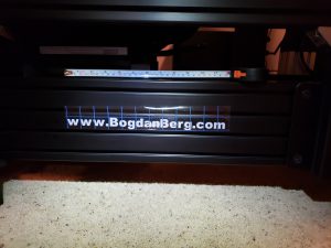
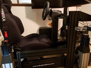
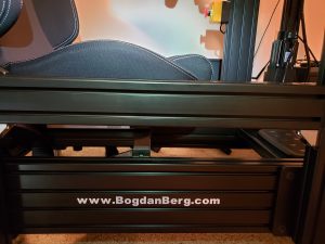
You’ve seen my extensive use of label maker through this series of articles. There’s one more thing you should know about me – I also like to make custom stickers. I decided to slap the URL onto both sides of the rig for an extra touch of personalization (and in case anyone had doubts I took those photos! 😉 ).
Simple thing – I cut them on a vinyl cutter from an adhesive vinyl, used transfer paper, aligned on the profiles (which I wiped beforehand) and made sure every letter adheres properly:
Next I’m probably going to add the driver flag and name decals… Stay tuned 🙂
SFX-100 Start/Stop button plugin
Small, yet amazing plugin. Allows for creating key bindings to start/stop the motion profile and adjust the intensity on the fly. Those are global key bindings, and work even if SimFeedback is not in the foreground.
Available here:
https://github.com/HoiHman/SFX-100-start-stop-buttonbox
SFX-100 Service Mode plugin
One more amazing plugin by HoiHman – super useful for testing the motion, both at the beginning after assembling it, as well as when fine-tuning the position (e.g. spacing for the monitor stand and monitors), as it allows us to extend the motion in each dimension. This way we can check the max height, left/right and forward/backward tilt to ensure sufficient clearance.
Available on Github repo:
https://github.com/HoiHman/SFX100-Service-mode-plugin
And a video showing service mode:
Video credit: HoiHman
Did you read all the way through 4 parts? If so, thank you and I hope you found it interesting! 🙂
Leave a comment and let me know if there’s something that you found especially valuable, or maybe you have any questions I could help with.
It’s been a fun project to build, and it’s a blast to use. The hardware (motors, ball screws, etc.) is stronger than what’s needed for this application (compare them with motors available in some ready to buy motion systems… 😉 ) and should last for a long, long time. Even 3D printed parts don’t show any signs of wear and tear. Plus with the thriving community around SFX-100/SimFeedback, support for more games, and the potential for further modifications (e.g. traction loss, seatbelt tensioner, Thanos controller and much more) – this is a platform that I believe will stand the test of time.
And I’m still amazed at times that now there’s a motion simulator at my home, and it didn’t cost that much after all… 😉
Thanks for reading!





Leave a Reply