Ahhh Christmas break! What a wonderful time of the year – too bad it goes by so quickly… 🙂
Anyways, to keep my brains occupied during time off from work (and, let’s be honest, have some fun geeking out!), I finally decided to build an arcade cabinet. I know, seems like everyone is building one, but that’s only because they’re so cool!
Here’s the final result:
For anyone visiting from Reddit, I also prepared an Imgur album, in case you may prefer that.
Please note that the description of the process is different in each case, so for most information I’d recommend reading both this post and the album on Imgur:
https://imgur.com/gallery/JgjLf
I started working on the project, as always, with a research, to look for inspiration, think various aspects through, and decide how I want to design my own cabinet.
But before I dive into details, let’s see what is needed to make one.
Bill of materials
- 1/4″ MDF sheets
- I had them cut to 24″ x 18″ as this is the max size I can use in laser cutter, and my design needs 6 sheets total.
- I was considering plywood, but I was discouraged by how difficult it became to find a straight sheets where I shop…
- Raspberry Pie 3, case, power supply, SD card
- Easily obtainable i.e. on Amazon, either in form of a complete set (I like this starter kit or a smaller and slightly cheaper version of the set) or as separate components: Raspberry Pi 3 Model B, case, power supply)
- 19″ LCD monitor, along with necessary cables
- The monitor I used had only DVI and VGA outputs, while Raspberry Pie has HDMI input, so I had to throw in DVI to HDMI adapter.
- Note that my design was driven by the dimensions of the bed for the laser cutter I have access to, and as such 19″ is the max size I could use. It doesn’t feel small though, given the distance from the screen.
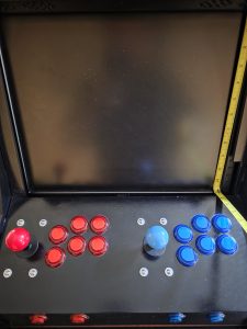
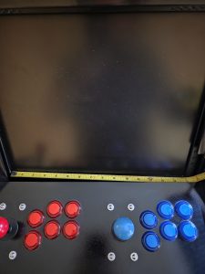
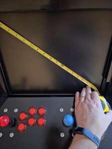
- Here are the exact dimensions of the screen: 19″ diagonal, 15″ width, 12″ height, 5:4 aspect ratio. The monitor itself is slightly larger including the bezels on each side.
- Small speakers
- I used USB-powered speakers, to avoid the need for one more power socket,
- Arcade joysticks and buttons
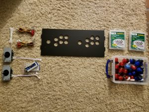
- Those can be easily purchased in kits, along with USB controller boards, cables with quick connect, etc.
- Here’s the set for 2 players I used,
- Extension cord (with 3 sockets),
- This one worked great for me,
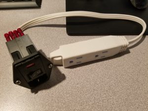
- “Kettle plug” socket with switch and fuse, along with quick connect plugs (insulated, safety first, especially when we move up from low voltage DC to AC), I picked mine from a local electronic store, but it’s also available on Amazon,
- Magnetic cabinet door catches
- I used those (they come with screws, but I ended up using bolts instead)
- Hinges,
- Primer, paint, etc. for the finished look you’re after,
- Various screws/bolts/nuts/washers (note: I used both metric [for VESA monitor mount] as well as imperial for all other needs and I feel like generally it’s good to have assortment of both handy 🙂 ),
- Optional: USB controllers for your favorite gaming system, if you’d like the ability to support more players, or just like their ergonomics 🙂
I used laser cutter to cut all the body panels, but more conventional tools could also be used instead 🙂 (jigsaw, band saw for button cutouts, etc.).
Design
You can find various designs easily online, or even buy pre-cut body panels to assemble your own cabinet (there are plenty to choose from on eBay), and then add hardware inside, but I like to make my own designs – it’s half the fun 🙂
It also gives you full control of all the aspects of the design, enables to re-iterate quickly to make improvements (i.e. for issues identified on the first fitting/test assembly), you don’t have to settle on compromises made by someone else (which could’ve been more applicable in their case) and in the end it just feels good to know that you made it all…
As always, I jumped into Fusion 360 and started sketching.
For this type of design, where we have side elements keeping all the pieces together (“sandwiched” in between), instead of designing each element separately (with its own “sketch”), I find it significantly more efficient to work off of a single sketch which defines dimensions of all elements and is a go-to place to make changes in sizes, relative positioning, etc. Then you can simply extrude the profiles from the master sketch into their own components.
Another decision I made early on was to include the tabs/slots in my design. Not everyone may like this approach (i.e. the side panels have visible tabs and are not a solid piece of wood, which affects aesthetics), but I like the ease of this approach for fitting the parts as well as convenience of final assembly and general sturdiness.
Also, I don’t have access to a bigger working space where I could arrange the elements and clamp them for hours… And with tabs/slots pieces just snap in together 🙂
Note that I skipped on the classic T-molding present in the original arcade cabinets. Unfortunately, I don’t have router table to accommodate those, and alternative solutions (gluing few panels with different sizes to have slot in the middle required for T-molding) didn’t seem worth it.
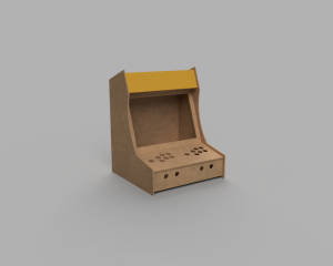
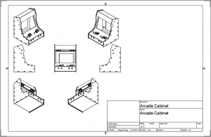
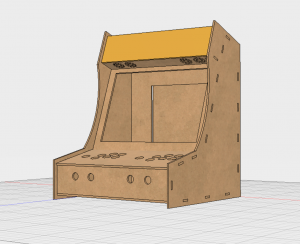
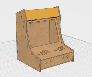
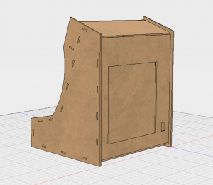
Here is the design I made:
And a short video showing how the separate elements are organized:
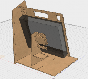
I continued to work on the design throughout, whenever I discovered something that could be improved. The biggest update was related to the monitor mount. At first I thought of using some kind of brackets to keep monitor in place (a problem I’d solve when I get there, thus not much thought in the initial design), but when doing first test assembly, I decided to also design a mount for the monitor, which would integrate with the construction and provide more support.
That was something I didn’t plan on doing at first, but now I feel that it made the design feel more complete, and assembly much easier. The cabinet feels very sturdy and I don’t have to worry about monitor shifting around, or becoming loose.
Making the cabinet
All the profiles of body panels were exported from Fusion 360 into .dxf file format and then cut on laser cutter from Universal Laser Systems.
Before committing to a large laser cutting job, I recommend doing few test cuts. This is especially helpful if you use tabs/slots as it can help you understand the impact of laser kerf and adjust your design dimensions if needed. Just make a small test piece with one tab and one slot and work off of that (to speed up the process and minimize the amount of wasted material). This is even more important when working with a new material.
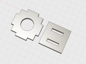
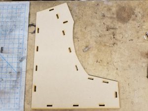
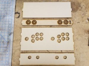
For reference, here are the parts I made for testing the dimensions and fitment of the tabs/slots and buttons (took me a quick 3 cuts to get the dimensions perfectly):
Cutting all the body panels took under 2 hours (this doesn’t include test cuts or iterations on the design, but is simply a total time if I were to go ahead now and cut the panels again in their final form).
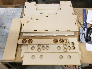
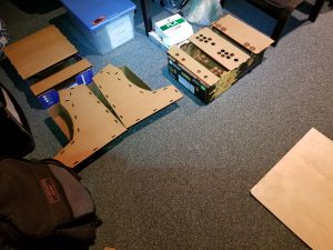
Panels fresh from laser cutter:
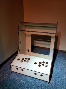
First assembly, to test the fitment of the parts, identify potential issues, etc. It’s better to make sure before we dedicate few hours into finishing the parts 😉
Installing the monitor
At this point I tried fitting monitor, and this is when I decided to do it the right way – design a strong, stable mount, instead of depending on some brackets and other flimsy solutions.
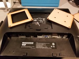
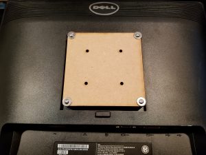
Monitors already come with VESA mounts, so it only seemed natural to take advantage of this fact. And this makes it possible to use different brands/models of monitors as well (potentially with some small adjustments, like different cutouts in the body panels to enable unobstructed access to the monitor’s control buttons).
Note that VESA mount uses metric screws, and the spacing between holes is not in inches (even though it’s very close to 4″, don’t be mislead, it’s actually 10cm – ask me how I learned that… 😉 ).
There’s one interesting property of VESA mount, which I took advantage of – they’re installed parallel to the screen. It means that I could easily define the angle of the mount to make sure that the monitor will be properly aligned with the front frame of the cabinet (since those are same angles).
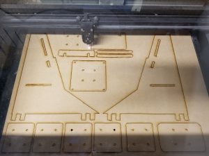
Laser cutter at work:
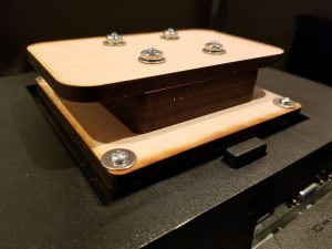
You may see that there are multiple instances of the same elements – those are used as spacers to allow me to position the monitor more to the front/back as needed.
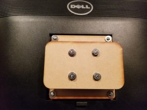
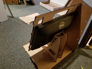
I screwed the pieces onto the VESA, and assembled the “head” of the mount. The “wings” at the end of the mount simply slide into 2 legs that are then attached to the base of the cabinet.
Notice that I’m using washers everywhere – MDF is quite a soft material, so I highly recommend using washers to make sure the connections are stronger.
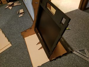
Making sure that the monitor fits nicely in the cabinet:
Notice a horizontal “beam” between the legs of the monitor stand. This serves 2 purposes: connects and stabilizes the legs for extra sturdiness, as well as serves as a simple shelf, to allow better organization of the internals.
EDIT 6/21/2025:
I’ve received number of inquries about the monitor dimensions over the years, and thought of confirming the exact dimensions of the one I used:
- 19″ diagonal, 15″ wide, 12″ high
Finishing the body panels
Since the panels were cut out of MDF, there’s one important thing to note: MDF absorbs finishes very quickly. As such, we’d either need to use layer after layer of paint, or first seal it. I decided to seal it with Shellac (following the principle of “Shellac sticks to everything and everything sticks to Shellac”). Two or 3 layers of shellac should seal MDF enough to continue with painting – it works great as a sealer and primer in one. It also dries very quickly.
Then I proceeded with painting the cabinet. I wanted for it to look… classy, nothing too crazy 🙂 So I went with black spray paint. Again, to be applied in fairly light coats, I ended up with 3 or 4 coats depending on the panel (I was making some adjustment in the design at this stage, thus some panels needed to be re-cut and started fresh).
To seal it off, I used a spray lacquer. I had few cans around so that seemed like a perfect application. I’m sure polyurethane would work just as well, if not better. I recommend light sanding between coats to remove all bubbles and uneven surfaces, in order to achieve the desirable mirror-like finish. It can be a scary thing to do (immediately after sanding things look significantly worse, so the first time around you’ll be pretty sure it’s destroyed), but don’t lose hope – it’s expected and it gets better with every next layer 🙂
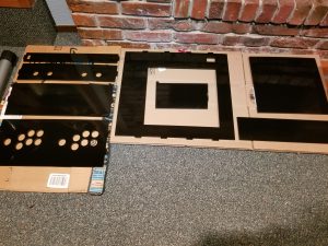
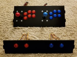
Body panels ready for finishing (first few layers of shellac to seal/prime MDF, then paint, and finally lacquer):
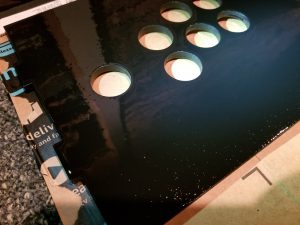
And somewhere in the middle of the process, between layers of lacquer. Notice the small bubbles still visible – those can be removed by sanding between the coats.
Note that all the panels except the 2 biggest side panels were painted only on 1 side, while the side panels were painted on both (there’s a “lip” sticking out for a 1/2″ from the edge of the side panels to the edge of every other panel attached to the sides, and we need to make sure that this lip also looks finished).
After all was said and done, I used 3 cans of Shellac, 2 cans of spray paint, and 3 cans of lacquer. More than I anticipated, so I’d recommend buying a bit more than you think you may need, to save yourself a shopping trip later on.
Electronics
If you’ve been looking at making an Arcade cabinet yourself before, there will be no surprises in this section for you 🙂
First task was to install and wire the joysticks and buttons. Do this after the wood has been finished, but before it’s all assembled into a cabinet 🙂
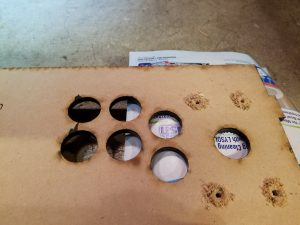
This is when I realized that I forgot to include screw holes for installation of joysticks, and even though I re-cut few panels previously after making changes in the design, I decided to solve this with a drill. I’ll be using washers here as well, so that gives me a wider margin of error if it so happens that the drill rips a bit of MDF on the finished side.
To minimize the risk of damage to MDF when drilling holes, use a piece of sacrificial wood underneath the MDF board. I used a piece of paper to protect the finished side of MDF from the wood underneath and drilled this way.
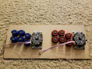
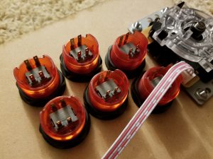
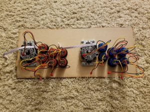
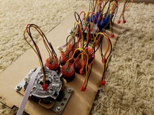
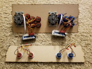
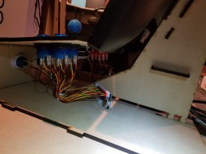
Time to install all the buttons and wires:
To make wiring easier and less error-prone, make sure that all buttons are oriented in the same way. This way it’s easier to keep connecting all wires in the same order.
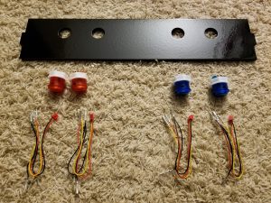
After connecting buttons on the control panel, it was time for the front panel, with Start and Select buttons:
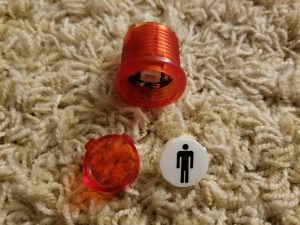
I added labels (P1, P2) to the faces of Start buttons. Those buttons can be disassembled easily by simply pushing in 2 tabs on the sides and pulling the face outwards.
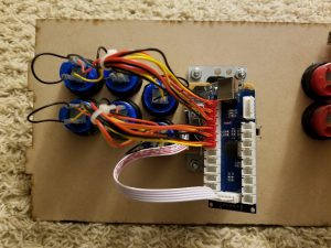
Everything wired and ready for assembly:
Final assembly and miscellaneous hardware
There were few additional pieces required to complete the cabinet.
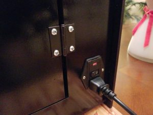
I started with the kettle plug, along with an extension cord (I used insulated quick connect clamps to connect those 2).
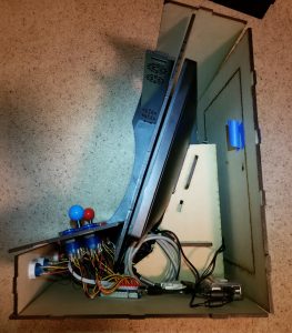
Then I added the heart of the machine – Raspberry Pi 3, and connected it all (RPi, 2x USB controller boards, power and video to the monitor, speakers):
For the door in the back of the cabinet, I used short “piano hinges”, with holes already cut on laser cutter (I updated original design to account for those, to avoid having to do more drilling later on):
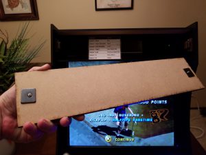
And to keep the door locked, as well as the front piece on the top of the cabinet (“marquee”) in place, I used the magnetic cabinet door catches:
I also hid a cheat-sheet with the global button shortcuts for RetroPie/EmulationStation in that bonus storage area 🙂
Software
I’m using RetroPie, and everything can be found at: https://retropie.org.uk/
I decided to use the ready image, so the complete setup was a breeze. Then just add roms of your choice (keeping mind the laws – generally it’s allowed to use ROMs of games you own physical copies of), and everything is ready! If you’d like to dive deeper into the configuration, different versions of emulators/BIOS, or customize the looks (splash screens, themes, etc.) the Wiki available on the official website is a great place to start: https://retropie.org.uk/docs/
There’s at least one alternative to RetroPie, but I didn’t have a chance to play around with it yet:
http://www.lakka.tv/
Photos of the completed arcade cabinet
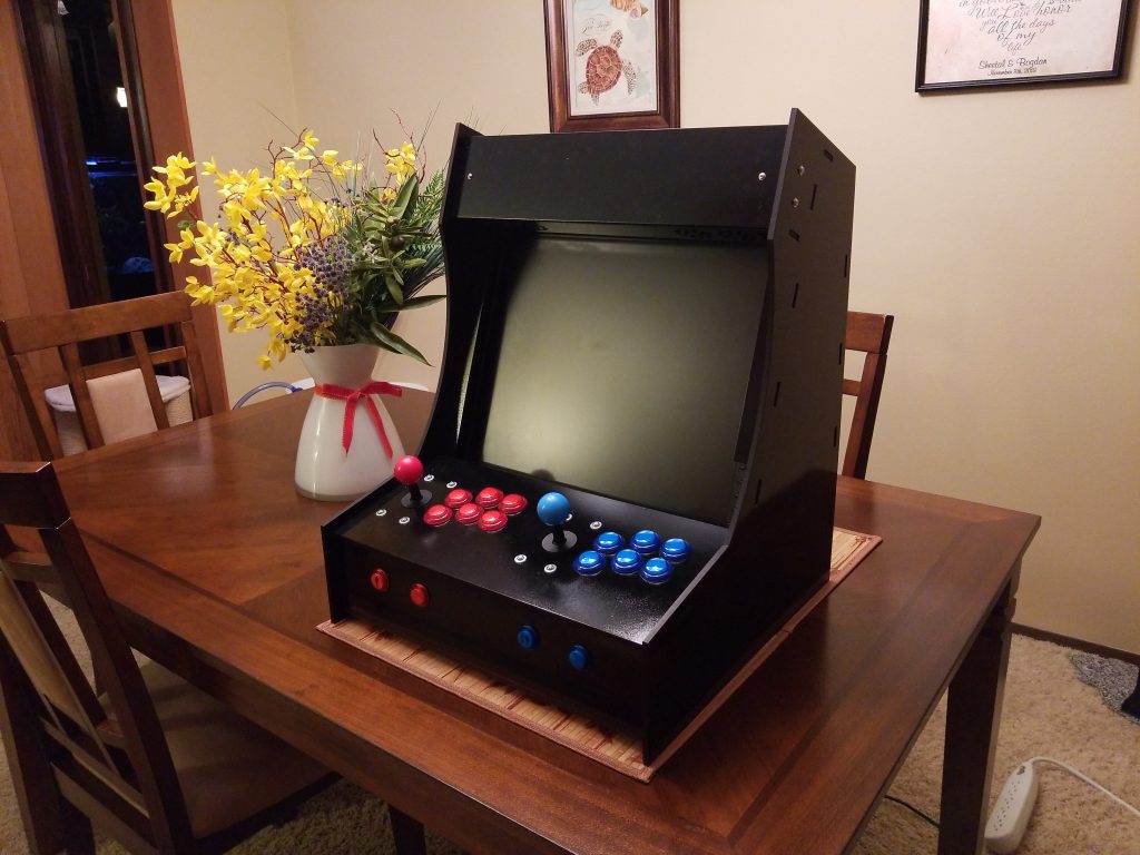
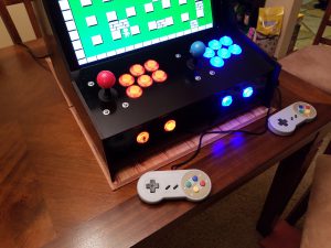
Finished look (along with some cool NES controllers on USB, to allow for up to 4 players!):
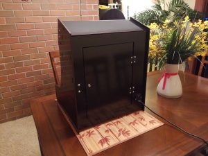
Look at the back:
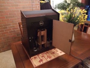
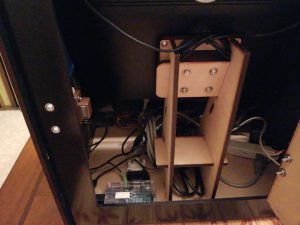
And inside:
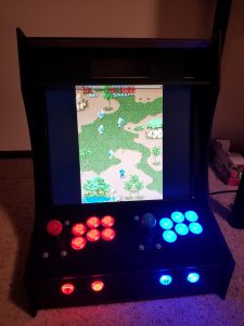
Ready to play!
Videos
Complete project:
First time booting after the assembly:
Special video with a celebrity making an unexpected appearance 🙂 (our yellow-sided green cheek conure, Bella)
Shared links:
Since I completed this project, it’s been featured on few websites:
- https://hackaday.com/2018/01/14/bartop-arcade-cabinet-build-skips-the-kit/
- https://redd.it/7quksm
- https://imgur.com/gallery/JgjLf
Looking for more inspiration?
If you’d like to read more on this subject, here are some interesting resources I found while doing my research:
- http://hein.htat.me/hugo/projects/pakupaku/1/ – my friend’s blog, he made an awesome, even more compact bartop cabinet for 1 player,
- http://www.instructables.com/id/2-Player-Bartop-Arcade-Machine-Powered-by-Pi/ – probably the most popular tutorial on making DIY arcade cabinets, a lot of useful information along with templates for body panels (if you don’t want to make your own design, etc.),
- http://www.instructables.com/id/Arcadia/ – nice collection of various DIY arcade cabinets,
- https://retropie.org.uk/ – everything about the emulation aspect of the arcade cabinet,
- http://www.lakka.tv/ – alternative to RetroPie,
If you build an arcade cabinet yourself, please share! 🙂



Leave a Reply